Bridging an eBUS Gas Boiler to Home Assistant with an Isolated ESP32
/ 8 min read
Table of Contents
Context
My home heating was previously governed by a basic dry-contact on/off thermostat relay. While functional, dry-contact control is completely blind: the relay clicks, the boiler fires up to its fixed dial temperature, and when the ambient room sensor is satisfied, it cuts off abruptly.
This on/off cycling creates thermal overshoot and hides critical operational health. It provides zero visibility into actual water circulation, flame modulation depth, burner short-cycling, or system hydraulic pressure. My unit is a DemirDöküm Ademix 24/28 condensing boiler—built on the Vaillant Group platform running the eBUS 2.0 physical and protocol standard (BAI00 motherboard). The boiler exposes a digital two-wire eBUS interface, carrying real-time telemetry from every internal transducer and actuator.
Rather than relying on closed vendor gateways, I set out to interface the boiler directly with my homelab. Coming from a systems administrator and DevOps background, my priority was not building an all-in-one “smart” gadget, but establishing a dependable, decoupled telemetry pipeline with clear failure domains. Here is how I designed the infrastructure, collaborated with my father on the analog hardware fabrication, and brought the telemetry into Home Assistant.
The Hardware and Electrical Isolation
Connecting a modern microcontroller to an HVAC bus requires careful electrical consideration. The eBUS standard operates on an open-collector signaling topology with high nominal voltages:
- Idle (Logical 1): ~20V to 22V DC
- Active / Dominant (Logical 0): ~9V to 12V DC
- Baud Rate: 2400 baud, half-duplex
Exposing a 3.3V ESP32 directly to these voltages would immediately destroy the chip. Connecting the heating system’s electrical ground directly to the homelab infrastructure would also introduce ground loops and electrical noise.
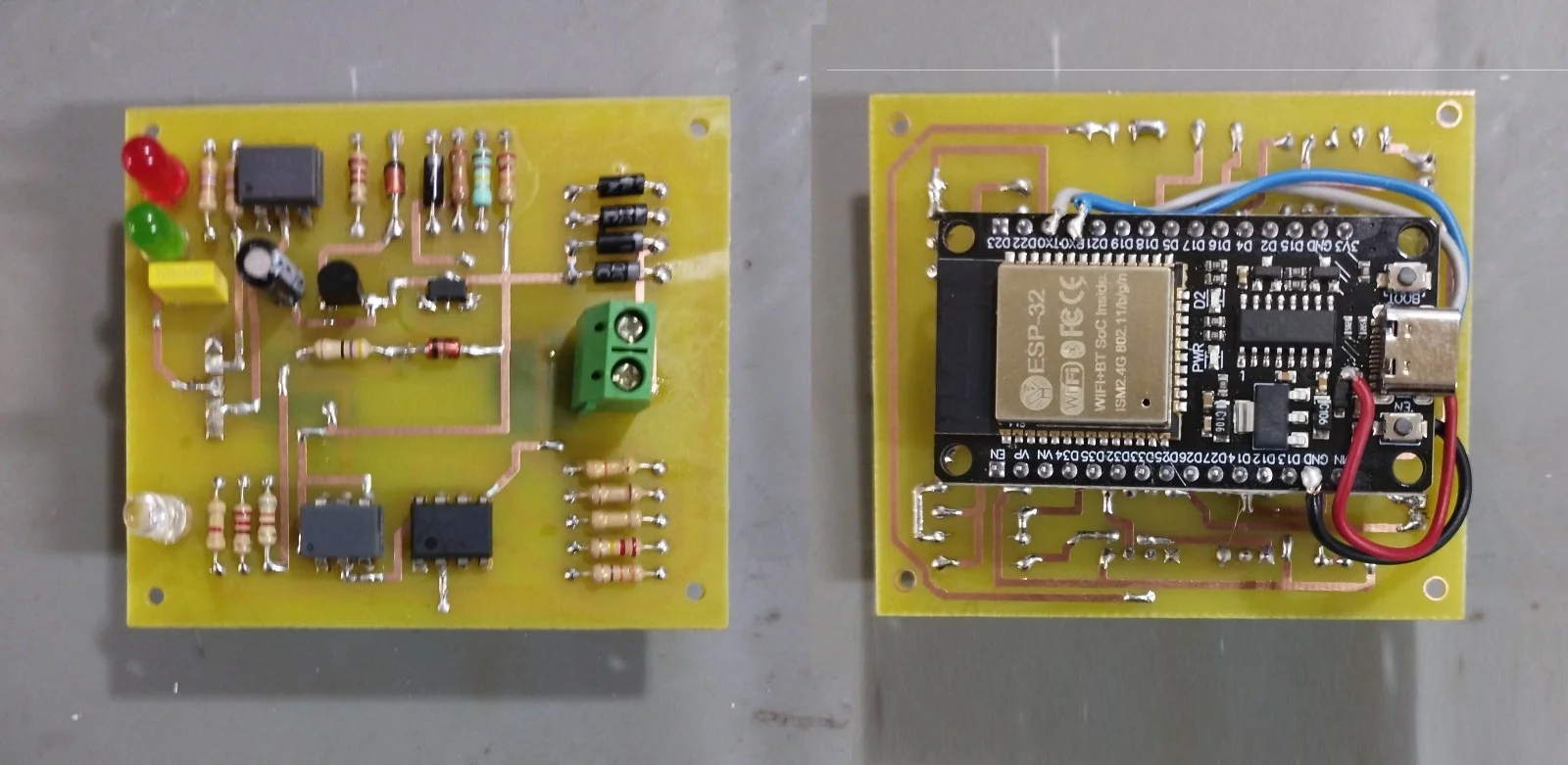
I followed the open-source eBUS Adapter v2.2 project design by John30, which uses an optocoupled level converter circuit proven across the ebusd community.
While my domain is software pipelines, networking, and system infrastructure, analog board fabrication is where my father stepped in. He custom-etched a single-sided copper PCB and populated the analog comparator and optocoupler circuitry, ensuring clean trace isolation and component layout. My focus was wiring the digital interconnects, securing the electrical boundary, and configuring the microcontroller bridge.
The design splits the interface into two completely isolated electrical domains:
[ Boiler eBUS Terminals (~21V DC) ] │ [ 1N4007 Bridge Rectifier ] │ ┌──────────┴──────────┐ ▼ ▼[ LM293 Comparator ] [ BC337 Transistor (TX) ] │ │ ▼ (Opto LED) ▲ (Opto Phototransistor) [ PC817 Optocoupler ] [ PC817 Optocoupler ]══════════════════════════════════════════════════ [ Galvanic Barrier ] │ (Collector) ▼ (Infrared LED)[ ESP32 GPIO16 (RX) ] [ ESP32 GPIO17 (TX) ] ▲ │[ 3.3V Rail (AMS1117 Regulated from 5V USB Supply) ]1. High-Voltage Boiler Domain
The boiler side connects via a 2-pin screw terminal. A diode bridge (four 1N4007 diodes) rectifies the input so polarity does not matter. An LM293 differential comparator paired with a 10V Zener diode reference reads the bus transitions without loading the line. Driving the line back to ground during TX transmissions is handled by a BC337 NPN transistor. This entire stage draws its tiny operating current parasitically from the 21V bus.
2. Low-Voltage Logic Domain
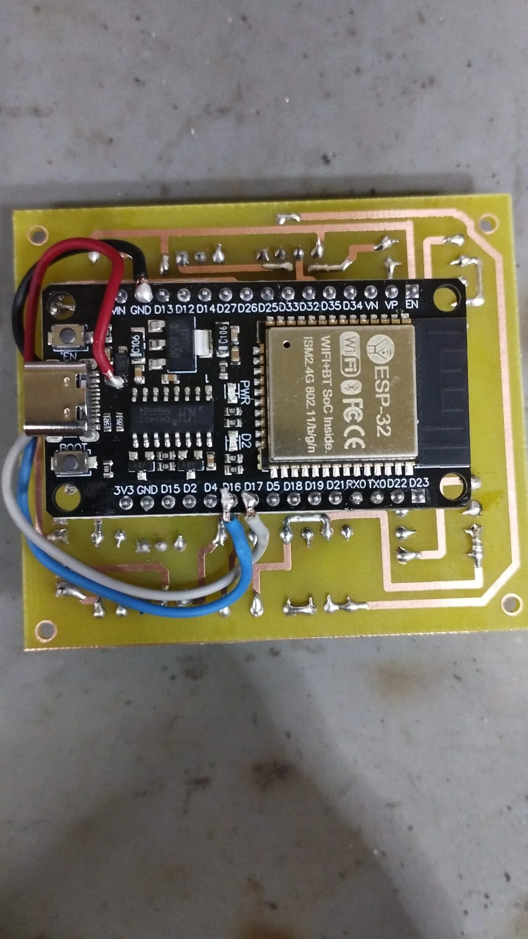
Two PC817 optocouplers transfer the serial bits across a physical gap using infrared light. The ESP32 is powered independently from a 5V USB wall adapter connected to a nearby outlet. The onboard AMS1117 linear regulator steps that down to 3.3V, which powers the microcontroller and pull-up resistors on the isolated logic side of the optocouplers. No copper path or common ground connects the boiler electronics to the ESP32.
Transparent TCP Bridge on ESP32
Approaching this with a DevOps engineering mindset, I deliberately kept the edge device as simple and stateless as possible. Running a monolithic heating controller or protocol decoder directly on the ESP32 would violate clean separation of concerns: an embedded firmware hang or memory leak could break telemetry collection or leave the connection hung. Instead, the ESP32 functions strictly as an infrastructure primitive—a transparent, bidirectional UART-to-TCP bridge running at 2400 baud.
I used ESPHome with the esp-idf framework and the native uart_tcp server component:
esphome:  name: ademix-ebus-bridge
esp32:  board: esp32dev  framework:    type: esp-idf
logger:
wifi:  ssid: !secret wifi_ssid  password: !secret wifi_password  fast_connect: true  power_save_mode: none  manual_ip:    static_ip: 192.168.1.240    gateway: 192.168.1.1    subnet: 255.255.255.0
api:  encryption:    key: !secret api_key
ota:  - platform: esphome    encryption:      key: !secret api_key
uart:  id: ebus_uart  rx_pin: GPIO16  tx_pin: GPIO17  baud_rate: 2400  rx_buffer_size: 1024
uart_tcp:  id: ebus_tcp_bridge  uart_id: ebus_uart  role: server  port: 9999  allowed_ips:    - 192.168.1.235
binary_sensor:  - platform: uart_tcp    uart_tcp_id: ebus_tcp_bridge    connected:      name: "ebusd TCP Connection"
sensor:  - platform: wifi_signal    name: "WiFi Signal"    update_interval: 60s
The firmware runs strictly as a passive listener on port 9999. It does not establish outbound network connections. Access is restricted using allowed_ips so that only my homelab host (192.168.1.235) can open the socket. Power-saving Wi-Fi modes are disabled (power_save_mode: none) to eliminate transmission jitter.
Protocol Decoding with ebusd
With raw serial bytes streaming over TCP, the parsing is handled by ebusd running inside Docker on my primary server (oneserver), hosted inside my modular homelab rack.
The daemon connects to the bridge socket, automatically scans the bus to identify connected hardware, fetches matching definition files (vaillant/08.bai.csv), and translates hex telegrams into readable values published over MQTT:
services: ebusd: image: john30/ebusd:latest container_name: ebusd restart: unless-stopped environment: EBUSD_LATENCY: "100" EBUSD_MQTTVAR: "filter-direction=r|u|^w,filter-name=waterpressure|flame|modulation|status|temp|error,filter-seen=2" ports: - "8888:8888" command: > --scanconfig -d 192.168.1.240:9999 --mqtthost=192.168.1.190 --mqttport=1883 --mqttint=/etc/ebusd/mqtt-hassio.cfg --mqttjsonSetting EBUSD_LATENCY=100 compensates for network round-trip time over the local Wi-Fi link. Upon connection, the daemon verified the bus handshake and matched the motherboard configuration:
[main notice] ebusd 23.3 started[bus notice] bus opened on 192.168.1.240:9999[bus notice] signal acquired[bus notice] scan 08: ;Vaillant;BAI00;5013;1303[bus notice] max. symbols per second: 120Because --mqttint=/etc/ebusd/mqtt-hassio.cfg was passed, ebusd registered over 90 MQTT discovery entities directly into Home Assistant without manual sensor definitions.
Operational Insights and Telemetry
Bringing digital bus telemetry into Home Assistant answered several diagnostic questions that were impossible to assess with an analog gauge or a basic relay.
1. Digital Water Pressure and Leak Analysis
In an analog pressure gauge, the difference between 1.1 bar and 1.4 bar is subtle and prone to parallax error. I noticed that the boiler pressure tended to drift down after being filled to 1.5 bar.
By polling sensor.heating_ebusd_bai_waterpressure_press at 0.01 bar resolution and analyzing the trend over seven days, the telemetry revealed that pressure leveled off at 1.21 bar into a flat horizontal plateau. Rather than a continuous negative slope indicating a water leak, the system simply sits naturally at 1.2 bar when cool.
I set an automation rule to send an alert only if the pressure dips below 1.0 bar, leaving ample time to top up the loop before hitting the boiler’s 0.8 bar low-water cutoff (F.22 fault code).
Pressure (bar)1.50 ──┐1.40 │1.30 └───┐1.21 └────────────────────────────────── (Stable Plateau)1.00 - - - - - - - - - - - - - - - - - - - - - (Early Warning Threshold)0.80 ━━━━━━━━━━━━━━━━━━━━━━━━━━━━━━━━━━━━━━━━━ (F.22 Hard Safety Lockout)2. Monitoring Real Condensing Efficiency
Condensing boilers only achieve their rated efficiency (>100% relative to lower heating value) when flue gases cool below their dew point (~54°C for natural gas), causing latent heat from water vapor to transfer into the return pipe.
With real-time flow temperature (status01_temp) and return temperature (status01_temp_1), I can calculate the thermal drop across radiators (ΔT):
- Return Water ≤ 45°C: Optimal condensing zone (~105% to 108% efficiency).
- Return Water 46°C – 50°C: Moderate condensing (~100% to 104% efficiency).
- Return Water > 54°C: Non-condensing mode (~92% standard efficiency).
Tracking this in Home Assistant confirms that automated flow setpoints derived from outdoor weather keep the return loop well below the 54°C condensation threshold.
3. Burner Modulation vs. Short-Cycling
The combination of sensor.heating_ebusd_bai_flame and sensor.heating_ebusd_bai_modulationdesired exposes the internal firing state.
During steady heating runs, the burner modulates cleanly between 25% and 40%, matching the building’s heat loss rate. When domestic hot water is drawn at a tap, modulation instantly ramps up to 80%–100%. Seeing this distinction prevents misdiagnosing brief burner stops as heating short-cycling.
The bridge has been running stably in my homelab, turning a closed heating appliance into a fully observable component of my home infrastructure.